كل يوم أقوم بنشر معلومة مفيدة أو فكرة جديدة أو نشاط جديد أو ابتكار . ستجد معلومات عن القراءة والكتابة والابتكارات والرياضة والطبيعة والزراعة وكل ماهو مفيد وجديد . ستجد معلومات عن طائرات الكوادكوبتر ومكوناتها وأحدث التقنيات الجديدة فى هذا المجال.
This is my outlet to the world. Here I put new post everyday.
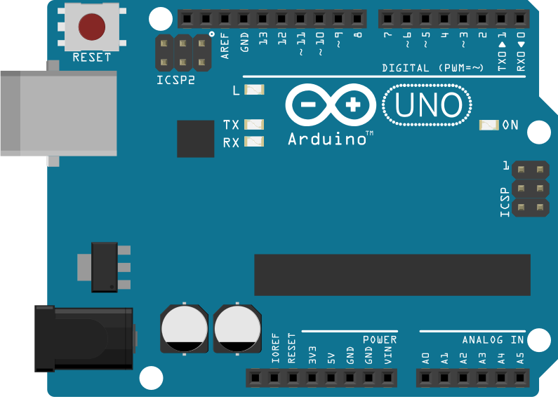
If you came to this post then you probably are an Arduino enthusiast and you want to make your own Arduino.
There are many Arduino compatible boards out there.
In this list you can find many Arduino compatible circuits and projects that are Atmel and Non-Atmel based. In this post, I'll show you an Arduino code compatible project that is based on PIC Microcontroller. Pinguino is a project based on PIC Microcontroller from Microchip Manufacturer. I'm a big fan of PIC microcontroller long before I knew Arduino. So once I knew about Pinguino I got excited to build it. It supports a wide range of Microcontrollers including 8 and 32 Bits. It has its own IDE but it's code compatible with Arduino. This means that you can use the code written for Arduino in your own Pinguino projects. Components
Today I found a simple circuit that uses Arduino and simple electronic components to measure and visualize heart rate.
There are many circuits out there that uses Arduino boards and a special heart rate sensor. Although I don't yet know the idea behind that heart rate sensor but I think it could be simple. That's why I searched further until I could find this simple circuit in this post. This circuit is so simple that it only contains Arduino board and IR transmitter and receiver as the heart rate sensor. I know this is very simple and primitive, but it's efficient. You can find many circuits with expensive sensors or larger circuits that use many amplifiers and OP-AMPs. But this one is fairly simple and enough for the job. Theory of operation The IR (infrared) transmitter and receiver are used to measure the blood flow which corresponds to the heart rate. The Arduino processor then processes the received signal and filters it to get a cleaner indication of the heart rate based on the blood flow in your finger. Components Arduino Uno IR emitter and detector 100 Ohm resistor 10K Ohm resistor Connections
Circuit
Code Arduino Code #include <FilterDerivative.h> #include <FilterOnePole.h> #include <Filters.h> #include <FilterTwoPole.h> #include <FloatDefine.h> #include <RunningStatistics.h> float amplifiedSignal; float filteredSignal; void setup() { Serial.begin(9600); } // filter out frequencies below 1 Hz. float highFilterFrequency = 1; // create a highpass filter that only keeps frequencies above highFilterFrequency FilterOnePole filterOneHighpass( HIGHPASS, highFilterFrequency ); // filters out frequenceies greater than 3 Hz. float lowFilterFrequency = 3; // create a lowpass filter that only keeps frequencies below lowFilterFrequency FilterOnePole filterOneLowpass(LOWPASS, lowFilterFrequency); void loop() { //The next line applies a band pass filter to the signal amplifiedSignal = 100*analogRead(A0); filteredSignal = filterOneHighpass.input(filterOneLowpass.input(amplifiedSignal)); Serial.println(filteredSignal);
}
Processing code import processing.serial.*; Serial myPort; // The serial porthe int xPos = 1; // horizontal position of the graph //int xPos = millis()/1000; //Variables to draw a continuous line. int lastxPos=1; int lastheight=0; int screenWidth = 600; int screenHeight = 400; int pulseNumber = 0; boolean pulseHigh = false; int startTime; int stopTime; int heartRate; void makeGrid(int screenWidth, int screenHeight){ stroke(0,255,0); strokeWeight(0.5); line(0, screenHeight/2, screenWidth, screenHeight/2); for (int i = 0; i <= 10; i = i+1) { line(i*screenWidth/10, 0, i*screenWidth/10, screenHeight); line(0, i*screenHeight/10, screenWidth, i*screenHeight/10); } } void setup () { // set the window size: size(screenWidth, screenHeight); // List all the available serial ports println(Serial.list()); // Check the listed serial ports in your machine // and use the correct index number in Serial.list()[]. myPort = new Serial(this, Serial.list()[0], 9600); // // A serialEvent() is generated when a newline character is received : myPort.bufferUntil('\n'); background(0); // set inital background: makeGrid(screenWidth, screenHeight); } void draw () { // everything happens in the serialEvent() } void serialEvent (Serial myPort) { // get the ASCII string: String inString = myPort.readStringUntil('\n'); if (inString != null) { inString = trim(inString); // trim off whitespaces. float inByte = float(inString); // convert to a number. if (inByte >= 0 && pulseHigh == false){ if (pulseNumber == 0){ startTime = millis(); //println("first"); } else{ stopTime = millis(); } pulseNumber = pulseNumber + 1; //println("next"); pulseHigh = true; } else if (inByte <= 0 && pulseHigh == true){ pulseHigh = false; } inByte = map(inByte, -1023, 1023, 0, height); //map to the screen height. //Drawing a line from Last inByte to the new one. stroke(255,0,0); //stroke color strokeWeight(4); //stroke wider line(lastxPos, lastheight, xPos, height - inByte); lastxPos= xPos; lastheight= int(height-inByte); // at the edge of the window, go back to the beginning: if (xPos >= width) { xPos = 0; lastxPos= 0; background(0); //Clear the screen. makeGrid(screenWidth, screenHeight); heartRate = 60*1000*(pulseNumber-1)/(stopTime-startTime); textSize(16); //text("This is your heart beat. Your heart rate is " + str(heartRate) + " bpm.", 10, 30); //fill(0, 102, 153); pulseNumber = 0; } else { // increment the horizontal position: xPos++; } }
Have you ever built an embedded system and wanted to store memory that lasts after you switch off the power of the system? Arduino boards is based around the AVR microcontroller that has built in EEPROM memory which is not volatile after you switch off the power of the circuit. This means that you don't need any external hardware or ICs when you need to store some small amount of data or system settings. Circuit When you test this code you only need Arduino UNO board as your circuit.
Code #include <EEPROM.h>
voidsetup() { for(int i =0; i <255; i++) EEPROM.write(i, i); }
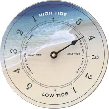
Tide clock is a clock that displays times to/past high and low tides instead of displaying real time.
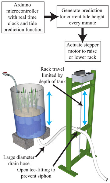
Inspired by the marine life, today I found a project that uses Arduino to simulate high and low tides into an artificial environment for marine life simulation. The project has both electronic and mechanical parts. The electronic part features Arduino and a real time clock to calculate tide times.
While the mechanical part features parts that control water flow and level into the artificial marine life environment.
In this post I found this instructable that makes a beautiful yet easy useful toy for your kids. Today I found an Arduino controlled model train that you can move using your phone.
We have seen how it's so easy to control devices using Arduino and Bluetooth module.
This projects implements that idea. It uses Arduino Nano as a controller and HC-06 Bluetooth module to connect to the smartphone. Then the train is driver by the L293D H-Bridge.
In this post we'll see how to generate audio signals from Arduino without using any shields or modules. PCM (Pulse Code Modulation)
Using Arduino and a speaker, you can generate audio signals as if they were coming out from an MP3 player.
Components
Arduino Uno
8 ohm Speaker
TIP 120 Resistor to be used as an amplifier.
Circuit
Just connect the amplifier transistor to Arduino and then connect them to the speaker. Software Download Audacity and then download software encoder from here. Arduino code is included in this file.
Have you ever made a project with Arduino and you loved it very much?
Have you ever felt for some project that it deserves to be built on a decent PCB, packaged in a robust enclosure and shown to the whole world?
You may be an Arduino enthusiast and try a project everyday with your favorite board. But hey ... You only have this single Arduino board that you got for $10 and you still want to try all those projects. You also have to make all those jumper wires look like spaghetti. What's the solution for this situation? The only solution for this is first by trying your design and prototyping it on your normal Arduino board. And then after the designing and refining process you transfer your design to a practical circuit using normal electronics based on the code you've just developed. So how can you use your Arduino code developed for Arduino Uno board of $10 to those ATtiny chips coasting $2?
Here is the solution. In this post you'll learn how to load Atiny with Arduino code using Arduino board as a programmer. This is very cool and has many advantages... 1 .You make your design more cost effective as you are using lower priced chips(if you already need only short number of input output pins. 2 .Your design is size efficient as you make it smaller and more practical. 3 .Your design becomes permanent on its own PCB. 4 . No need for new code or software as you are already using code you've just developed for Arduino board. 5 . No need for special programming circuits and loaders as you use only Arduino board as a programmer and Arduino IDE as the software loader. So let's see how this is done. This project is based on the High-Low Tech Program tutorial from MITthat describes in detail how to program ATtiny 45/85 with Arduino.
In this post we'll learn how to use ArduDroid to control Arduino board in two way communication via Bluetooth using Android smartphone. This Android App uses Bluetooth to connect Arduino to Android phone using serial Bluetooth Module HC-05 or HC-06. Using this App, you can read and write to and from all Arduino board pins and ports. You can read and write to digital ports, you can control PWM ports to write Analog signals, read Analog values from Analog ports and read/write serial data to the Arduino board.
By connecting Arduino board to the Bluetooth module you can gain full control of it. Normally, the code is opensource so the solution can be customized to your needs and configuration. Components Arduino Board Bluetooth Module HC-05 or HC-06 Android Phone ArduDroid App Connection Connect Arduino to the Bluetooth module as the author has chosen or use your own configuration by changing the Arduino code.
Circuit
Code
/*
 PROJECT: ArduDroid
 PROGRAMMER: Hazim Bitar (techbitar at gmail dot com)
 DATE: Oct 31, 2013
 FILE: ardudroid.ino
 LICENSE: Public domain
*/

#define START_CMD_CHAR '*'
#define END_CMD_CHAR '#'
#define DIV_CMD_CHAR '|'
#define CMD_DIGITALWRITE 10
#define CMD_ANALOGWRITE 11
#define CMD_TEXT 12
#define CMD_READ_ARDUDROID 13
#define MAX_COMMAND 20  // max command number code. used for error checking.
#define MIN_COMMAND 10  // minimum command number code. used for error checking.
#define IN_STRING_LENGHT 40
#define MAX_ANALOGWRITE 255
#define PIN_HIGH 3
#define PIN_LOW 2

String inText;

void setup() {
  Serial.begin(9600);
  Serial.println("ArduDroid 0.12 Alpha by TechBitar (2013)");
  Serial.flush();
}

void loop()
{
  Serial.flush();
  int ard_command = 0;
  int pin_num = 0;
  int pin_value = 0;

  char get_char = ' ';  //read serial

  // wait for incoming data
  if (Serial.available() < 1) return; // if serial empty, return to loop().

  // parse incoming command start flag
  get_char = Serial.read();
  if (get_char != START_CMD_CHAR) return; // if no command start flag, return to loop().

  // parse incoming command type
  ard_command = Serial.parseInt(); // read the command

  // parse incoming pin# and value
  pin_num = Serial.parseInt(); // read the pin
  pin_value = Serial.parseInt();  // read the value

  // 1) GET TEXT COMMAND FROM ARDUDROID
  if (ard_command == CMD_TEXT){
    inText =""; //clears variable for new input
    while (Serial.available())  {
      char c = Serial.read();  //gets one byte from serial buffer
      delay(5);
      if (c == END_CMD_CHAR) { // if we the complete string has been read
        // add your code here
        break;
      }
      else {
        if (c !=  DIV_CMD_CHAR) {
          inText += c;
          delay(5);
        }
      }
    }
  }

  // 2) GET digitalWrite DATA FROM ARDUDROID
  if (ard_command == CMD_DIGITALWRITE){
    if (pin_value == PIN_LOW) pin_value = LOW;
    else if (pin_value == PIN_HIGH) pin_value = HIGH;
    else return; // error in pin value. return.
    set_digitalwrite( pin_num,  pin_value);  // Uncomment this function if you wish to use
    return;  // return from start of loop()
  }

  // 3) GET analogWrite DATA FROM ARDUDROID
  if (ard_command == CMD_ANALOGWRITE) {
    analogWrite(  pin_num, pin_value );
    // add your code here
    return;  // Done. return to loop();
  }

  // 4) SEND DATA TO ARDUDROID
  if (ard_command == CMD_READ_ARDUDROID) {
    // char send_to_android[] = "Place your text here." ;
    // Serial.println(send_to_android);   // Example: Sending text
    Serial.print(" Analog 0 = ");
    Serial.println(analogRead(A0));  // Example: Read and send Analog pin value to Arduino
    return;  // Done. return to loop();
  }
}

// 2a) select the requested pin# for DigitalWrite action
void set_digitalwrite(int pin_num, int pin_value)
{
  switch (pin_num) {
  case 13:
    pinMode(13, OUTPUT);
    digitalWrite(13, pin_value);
    // add your code here
    break;
  case 12:
    pinMode(12, OUTPUT);
    digitalWrite(12, pin_value);
    // add your code here
    break;
  case 11:
    pinMode(11, OUTPUT);
    digitalWrite(11, pin_value);
    // add your code here
    break;
  case 10:
    pinMode(10, OUTPUT);
    digitalWrite(10, pin_value);
    // add your code here
    break;
  case 9:
    pinMode(9, OUTPUT);
    digitalWrite(9, pin_value);
    // add your code here
    break;
  case 8:
    pinMode(8, OUTPUT);
    digitalWrite(8, pin_value);
    // add your code here
    break;
  case 7:
    pinMode(7, OUTPUT);
    digitalWrite(7, pin_value);
    // add your code here
    break;
  case 6:
    pinMode(6, OUTPUT);
    digitalWrite(6, pin_value);
    // add your code here
    break;
  case 5:
    pinMode(5, OUTPUT);
    digitalWrite(5, pin_value);
    // add your code here
    break;
  case 4:
    pinMode(4, OUTPUT);
    digitalWrite(4, pin_value);
    // add your code here
    break;
  case 3:
    pinMode(3, OUTPUT);
    digitalWrite(3, pin_value);
    // add your code here
    break;
  case 2:
    pinMode(2, OUTPUT);
    digitalWrite(2, pin_value);
    // add your code here
    break;
    // default:
    // if nothing else matches, do the default
    // default is optional
  }
}
 enthusiast and you want to make your own Arduino
 .
.


![A Trip To Siwa Oasis: Tourist guide to an Egyptian Oasis by [ElSakhawy, Sara M.]](https://images-na.ssl-images-amazon.com/images/I/51-IGAzLKML.jpg)
![The Ultimate travel bag list by [ Elskhawy, Sara M.]](https://images-na.ssl-images-amazon.com/images/I/51OlVgqIcwL.jpg)
![Why to Travel?: Travel Like an Insider by [M., Sara]](https://images-na.ssl-images-amazon.com/images/I/51BsVhmk3ZL.jpg)
![3 Easy steps to plan your trip: Travel Like an Insider by [Elskhawy, Sara M.]](https://images-na.ssl-images-amazon.com/images/I/51GRc%2BnSxAL.jpg)
![Solar Artwork: How to Make Your Own Solar Masterpiece by [Ebeed, Ahmed]](https://images-na.ssl-images-amazon.com/images/I/51wT6i0RXNL.jpg)
![Backyard Wind Turbines: Harness wind power with simple and fun projects by [Ebeed, Ahmed]](https://images-na.ssl-images-amazon.com/images/I/51JEcdMP8JL.jpg)